Front Bii Board -- Full_Board_6.jpg
The Bii Board
sensory technology, powered by you
Increase font on mac use Option Command +
Increase font on pc use Control +
The Bii Board is part of a program to develope sensing technology. This program uses Acoustic Cybers (which are short acoustical sounds that can convey an enormous amount of information) and micro computers and micro sensors to help the blind and others sense their enviroment.
Developing the earlier prototypes, the associated hardware, fixturing, wiring, packaging, interfaces, reliability and communication between boards and other groups was an effort commensurate with the software and electronic design effort. The Bii Board is designed to help solve these problems by providing the physical platform, much of the wiring, convenient interconnections and enhanced reliability. To find out more about other parts of this program, please click the "Jump to Initial Main Page" above. We hope to have you join us in our endevor.
Front Bii Board -- Full_Board_6.jpg
What would you do, if you could do anything? The Bii Board is sort of my answer to this question.
During the many earlier versions of this project the hardware fixtures, wiring, cramming things together, redesigns, and other hardware problems were a comparable effort to the software. Would it not be lovely if there was a board with a place for everything and everything in it's place. When I actually started designing the Bii Board, it was like the Bii Board was pulling me along. A place for the computers please, and access to the signals, oh interfaces, and don't forget mounting holes. And a place for the sensor breakout boards. Oh, don't forget a way to move signals to other boards. And add mounting holes, lots please. Oops, this doesn't fit here, what if I swap these two? Then the hard questions. The board is too large. There is a little extra space, what goes there? Finally it got to the place where I was making silly little changes. Please, tis time to stop. -- Now that it's designed, I can't wait to use it. However, I have to finish this white paper first.
So, now the job is to explain the Bii Board. I'll try to keep it a simple. Most of the people using the Bii Board can probably figure how to use it themselves anyway. So I will give the big picture. If in doubt, grab an Ohm meter.
The details are below.
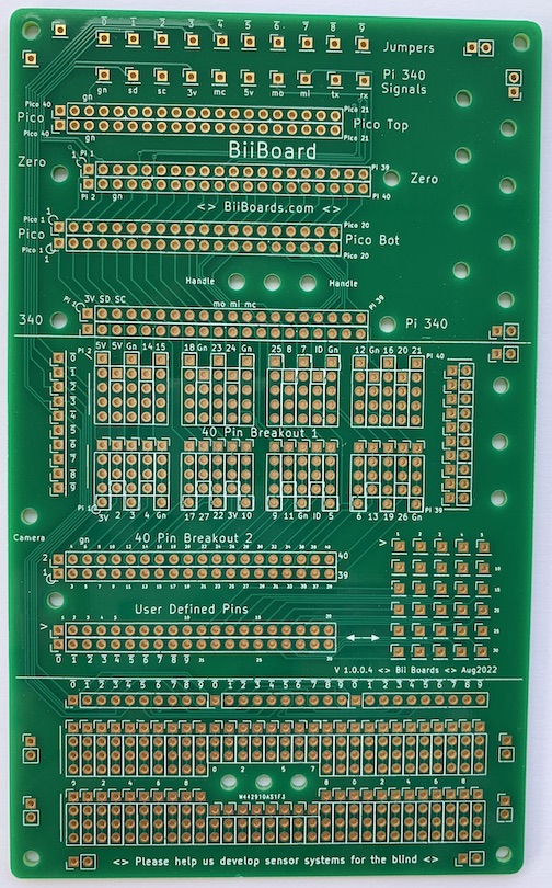
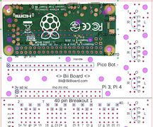
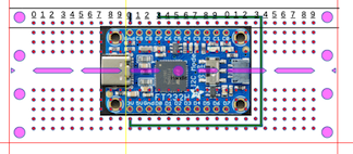
The top section of the Bii Board is shown below, first empty, next with the Pi 3 or 4 computer connected, then with the Pi Zero, and finally with the Pico. These signals are also available in the middle section. The top section is also designed so the edges of the Bii Board align with the edges of the computer being used. This makes it easy to plug in things. The top section also has a row of Jumpers discussed later. For convenience we will refer to the Pi 3, and Pi 4, and Pi Zero computers as Pi 340. The Pi 340's output pins have identical signals. (Pictures are take from several different versions.)
Top Empty
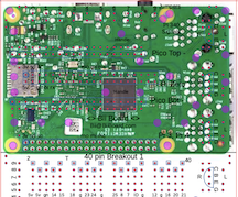
Pi 340 (Pi 3, Pi 4 or Zero)
Pi Zero
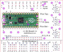
Pi Pico
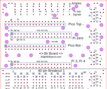
The millipede in the center of the figure below makes all the signals from the computer available for breadboarding. If a Pi 340 computer is conneted, the BCM numbers (Broadcom computer) and other functions are shown above and below the millipede holes. For example the upper left legs of the millipede are 5 V, 5 V, GND, BCM 14, and BCM 15. The upper left leg is physical pin number 2. The Pico has completely different numbering and the Pico upper left legs are numbered 40, 39, 38, 37, 36.
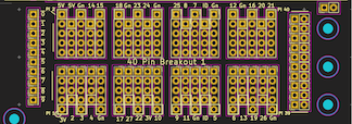
Top of Middle Section Showing the Millipede (40 Pin Breakout 1) @Millipede4-5.png
To the left of the millipede are the Jumpers. These holes are also replicated in the top and bottom sections as shown below. All of the 0 holes are interconnected, and all of the 1 holes interconnected ... . Having the commonly used signals available in each section makes wiring easier, reduces the mess of wires and makes trouble shooting much easier. Also large ground or supply currents can be carried around the Bii Board with wires between these Jumpers.
To the right of the millipede are a series of holes that can conveniently connect eternal wires to the Bii Board. The red line on the top set of holes shows the interconnections. The blue circles show holes available for 2-56 or m2.5 mounting screws.
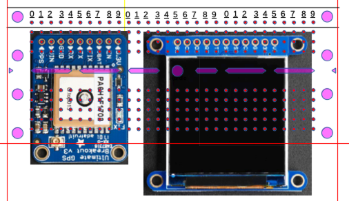
The figure below shows the bottom of the middle section of the Bii Board. The 40 Pin Breakout 2 shown has the same pinout and orientation as the millipede and can be used to transfer these signals to another board. For example, an Adafruit 2822 can be soldered into these holes and an Adafruit 1988 ribbon cable used to transfer the signals to another Bii Board or to another breadboard.
In a similar manner, the User Defined Pins can be used to move other signals off the Bii Board. The array-of-holes to the right provide a convenient way to connect to these User Defined Pins. Here the small numbers show the connection between the User Defined Pins and the array-of-holes. For example in the User Defined Pins the pin labled 5 is connected to the array-of-holes labled 5. Also note that the Jumpers are also available on the bottom left of the User Defined Pins.
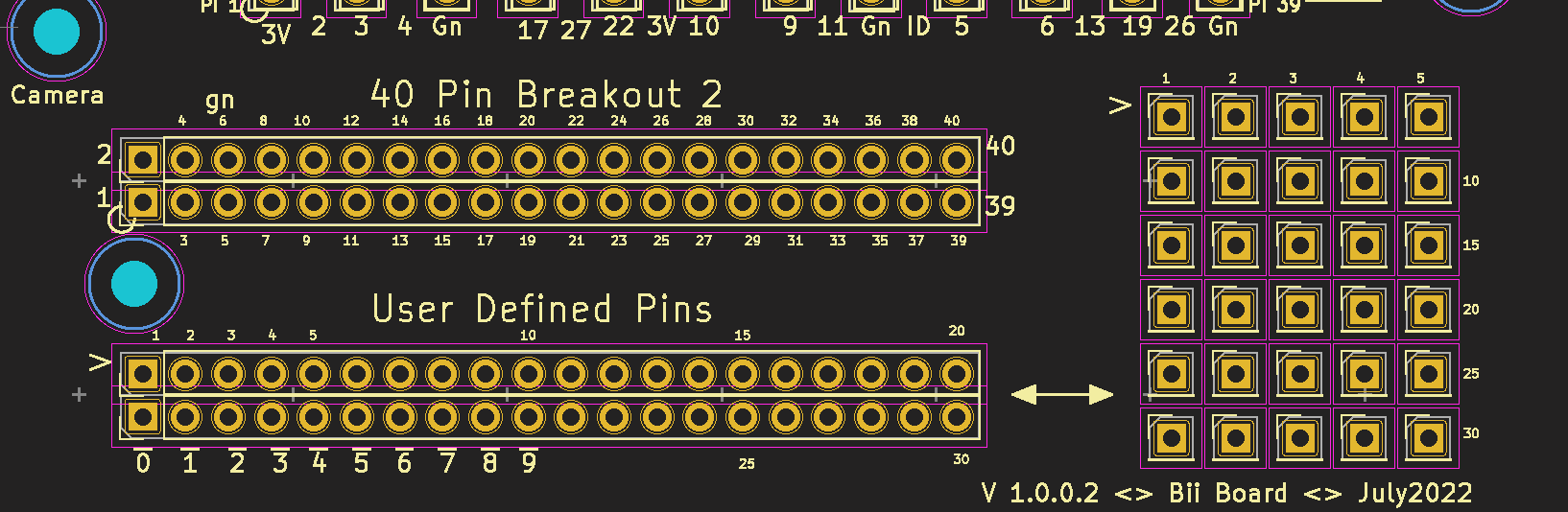
Lower Portion of the Middle Section -- Communication with Other Devices @Millipede4-5.png
The Jumpers and Pi 340 Signals in the Top Section of the Board
Commonly used computer signals can be easily connected to the Jumpers using the holes below the Jumpers (in the upper section). For example, the ground signal from a Pi 340 computer is made available at the hole labled gn. Connecting gn to 0 makes the ground available on all 0 holes. The other computer signals are SDA1, SCL1, 3.3 V, SPI_CLK, 5 V, MOSI, MISO, TXDO, RXDO. Below is a table giving the Pi 340 signal name, the pin number, and the function. Also given is the pin number if a Pico computer is connected.
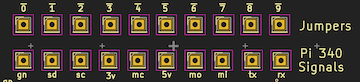
Jumper Wires in the Top Section -- @Jumpers_Top5.png
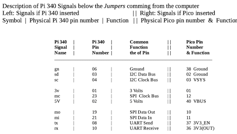
Table of the Pi 340 and the Pico Jumper Signals
There are so many different ways to use the bottom section of the Bii Board, it is hard to describe. So, I think it better to give examples.
The Green and Black Wires Show the Breakout Board Connected to Power and Ground @Bottom1.png
A GPS System and Display @Bottom2.png
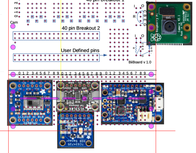
Loaded for Bear, Many Sensors in Use @Bottom3.png
Every One is Needed -- To Make It Grand