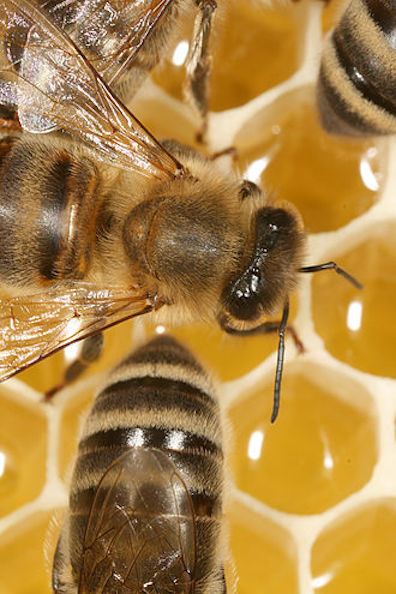
Many Bees Make Work Light -- Bee1_6.jpg
Acoustic Cyber White Paper
sensory technology, powered by you
Increase font on mac use Option Command +
Increase font on pc use Control +
Acoustical Cybers are short distinctive bits of sound which can be used to transmit large amounts of information to the blind and others. These sounds might be musical notes, bits of bird chirps, electronic music, sounds from nature or other distinctive sounds.
The brain has an amazing ability to recognize the sounds of our lives. Microcomputers have the ability to generate these sounds and there are a plethora of microsensors that can measure distance, colors, temperatures, GPS locations, six dimensional rotations in space, ... . This white paper discusses how to sense the environment, process the data into useful information, and communicate with the user using Acoustical Cybers.
There are 3 parts to this white paper. The first discusses the Acoustical Cybers in more detail. To make these systems available, the skills from many different disciplines are needed. The second section discusses how to form collaborations to make this happen, and how to easily transfer technology using the Bii Board. And the third section discusses how to go through the phases of Research, Developing and Manufacturing Production to make useful devices available to the blind.
This has been a quiet, ongoing development for several years, and it has become apparent that a broader range of skills is needed. Your thoughts are most welcome.
Many Bees Make Work Light -- Bee1_6.jpg
I've had an interesting journey. It started when I saw a clip of a blind person using echolocation. I've taught acoustics, and what he was doing seemed impossible. As I read, I became more and more amazed by the human auditory system. Indeed, perhaps our hearing is the only sense that uses all parts of the brain simultaneously. The more I read, the more marvelous it seemed.
I set upon making a system that used a card sized microcomputer, the host of available microsensors, and acoustics as a way to communicate the environment to the blind. I have been at it for a while, and failed quite successfully. As I worked on the project I came to understand what an extensive project it is, and that it involves many different disciplines. I still believe these system could be quite helpful to the blind and others, and have decided to ask a few friends to join me. I hope you find it interesting. (Note 2/28/2023 A successful failure is when one fails, finds a better approach, and goes back at it.)
First with the acoustic part of the system. The human brain is very adept at recognizing different acoustic sounds. I'd wager a whole cup of coffee, that you can recognize a million or so different acoustical sounds, or Acoustic Cybers, and associate distinct things with each sound. As an illustration, let's discuss piano notes.
The piano has 88 keys. Most human alphabets have between 20 and 40 characters. So, it made sense to start with 40 notes. (This research is preliminary, and I've been running pretty hard to put my foot in all the areas.) There are number of considerations in choosing the 40 notes -- some notes provide better stereo, low frequency notes tend to take longer to recognize, consonance and dissonance are different for different frequency ranges, and so on. A bit arbitrarily, the 40 notes between C2 and D#6 were chosen for the 40 notes. There are a surprising number of ways these notes can be combined.
For example, we could use a single note, or combine the notes making a two note chord, either major or minor. Or we could make 3 note chords, again major or minor. From some early experiments we made, it appears the human ear can discern between the notes of a chord being played simultaneously and a chord where one of the notes has been delayed by 14 milliseconds (0.014 seconds). These experiments suggested there are many other delays that make distinctive sounds. But for the moment, lets assume only the 14 millisecond delay is used. And so, there are 40 notes, and there are 9 ways to make Acoustical Cybers out of each note.
40 Notes The piano notes between C3 and D#6 {C3 C#3 D3 D#3 E3 F3 F#3 G3 G#3 A3 A#3 B3 . . . D6 D#6}
9 chords 1 note, 2 note and 3 note chords in major and minor, plus the 14 millisecond delayed chords
With two ears (ie two microphones) one should be able to discern the direction of sound along the azimuth (direction along the horizon), because sound coming from different azimuth directions arrive at the two ears at different times. Surprisingly, the observer can also tell how high the sound is above the horizon. That is because of the sensitivity of the ear's pinna to different frequencies (the pinna is the portion of the ear that sticks out from the head), and to the refraction of sound around the head, the reflection off the shoulders, and other effects. Here we will only assume the observer can detect directions from the right, left, straight ahead, the 45 degree directions on either side of straight ahead, behind the observer, and above the observer, giving 7 directions. We will also assume the ear can discern 4 different volumes, and 4 different durations of the sound. The trained ear can probably do much better. And there are at least ten different musical instruments that can be used instead of the piano.
7 Azimuth and Altitude
4 Volumes
4 Durations
10 Different musical instruments
And now for a little bit of math. It's simple, but you can skip this section.
If a single die is thrown on a table, there are six possible faces that could be up, 1, 2, 3, 4, 5, 6. This forms a set of 6 possible states {1 2 3 4 5 6}, which is the sample space of the first die. If a second die is also thrown, it has it's own sample space, {1' 2' 3' 4' 5' 6'}. If they are thrown together, there is now a sample space of 6 x 6' = 36 possible states for the dice on the table, ie, {1,1' 1,2' 1,3' 1,4' 1,5', 1,6' 2,1' 2,2', ... }.
If a coin is also thrown on the table, its sample space is {1 2}. The result of the coin and dice throws are independent (or orthogonal). (We could, for example, say three blindfolded people threw the dice and coin.) The total number of possible unique states on the table are 6 x 6' x 2 = 72, (that is because there are 36 possible states of the dice when the coin is heads up, and 36 possible states when the coin is tails up).
Now if an instrument has 6 different notes, and each note can be played at one of 4 different volumes, there are 24 different sounds that instrument can play 6 x 4 = 24. Fortunately, as you will see, there are a number of independent ways to modify a musical note. This will give a huge number of distinctive sounds. Examples of ways to modify a note are volume, duration, stereo, combinations of notes, and others.
As with with our discussion above, the number of unique states of the 40 notes (Acoustical Cybers), is just the product:
40 x 9 x 7 x 4 x 4 x 10 = 403,200 possible unique sounds
Hence there are over a third of a million distinctive sounds one can make with our 40 notes.
One can quibble with the assumptions above. But what one can't quibble with is, there are a huge number of distinctive sounds that can be made with the 40 musical notes.
Suppose we combine two of the Acoustical Cybers above into a short burst of sound. The number of distinctive sounds is 403,200 x 403,200 = 162,570,240,000 which is the astronomical number, 162 billion. That's more than all the stars in the Galaxy. As a reference, Merriam-Webster's Collegiate Dictionary has 225,000 definitions. Properly designed, a set of Acoustical Cybers can be quite expressive.
We have just scratched the surface of possible sounds and phonology. The National Audubon Society has recordings of 2500 bird calls. Each of these calls can be played at different speeds to make different notes. (<> https://musicofnature.com/audubon-bird-songs). Electronic music can also make an enormous number of distinctive sounds. My car has a vast and increasing number of sounds. My brain recognizes each car sound. Let a new sound creep in, and it is blatantly obvious to me as I drive. Interestingly enough, my passengers usually can't hear the new sound. This is because they are not familiar with my car, and the ear is most proficient with sounds it has heard before. Ethnomusicologists work with many other musical scales and instruments. Other creatures from whales to crickets have their distinctive sounds which they use to communicate. The basic sounds from all the world's different languages could be used as Acoustical Cybers; also look up fast talkers John Moschitta Jr. and Steve Woodmore. The range of possible Acoustical Cybers is, well, larger than I can imagine.
The other day I was asked, "what is the color of the tip of candy corn?" I have eaten candy corn for over 70 years, but did not know the answer. Yet if the tip colors of a box of candy corn had changed, I would know it in an instant. It appears my brain has two ways to deal with color images. One is noticing and comparing the color of the pixels in the image. The second, is to recognize objects. And the brain has an amazing facility with this. The blind, I suspect, want to know about the colors in the image and also the identity of the objects in the image.
Fortunately Artificial Intelligence has developed great ability recognizing an object and the object's characteristics. For example, the user may want to know about a car's location, speed, color, type of vehicle (bicycle, car, or truck), and it's probable path. It is quite cumbersome to try and say all this information quickly. It is my contention, all of the information generated by Artificial Intelligence can be presented rapidly using Acoustical Cybers.
Most of the Acoustic Cybers I use have a duration of between 500 and 850 milliseconds (0.500 and 0.850 seconds). Some sounds, like the gong of an Apple computer booting up, last longer. I typically use 1200 to 1600 milliseconds for these longer sounds. -- I suspect one could actually use shorter durations for all these sounds.
Let me use color as an example. Suppose for example, the observer had a camera that gave the color at the center of the camera's image. (Maybe the person is following a red brick path.) This color can be communicated using the 40 piano notes above. For example, using the Hue, Saturation, and Value notation (Color, Amount of White, and the Brightness), the Hue can be represented by the note, the Saturation represented by the chord structure (major, minor, 2 note, 3 note, 14 millisecond delay) and the Value represented by the loudness. In earlier work I had trouble representating pastel colors using this HSV notation. Indeed, when the values of the red, green, and blue were almost the same, the hue changed rapidly for small changes of color. Currently I am using the RGB notation (Red, Green, Blue), with the pitch of three sequential notes representing the amount of the red, of the green and of the blue. This is working better. There is much more to explore.
Color gives an interesting example of a multidimensional sense. Dimensions that I have had little chance to explore because I have been wrestling with the hardware.
A dream of mine is to show a blind person the colors of the setting sun.
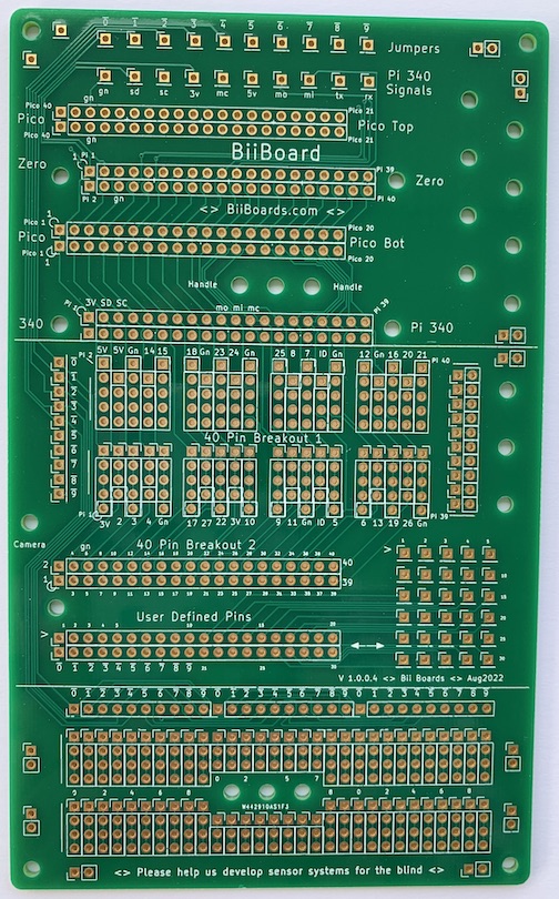
Front of the Bii Board -- Full_Board_6.jpg
What would you do, if you could do anything? The Bii Board is sort of my answer to this question.
During the many earlier versions of this project the hardware fixtures, wiring, cramming things together, redesigns, and other hardware problems were a comparable effort to the software. Would it not be lovely if there was a board with a place for everything and everything in it's place. When I actually started designing the Bii Board, it was like the Bii Board was pulling me along. A place for the computers please, and access to the signals, oh interfaces, and don't forget mounting holes. And a place for the sensor breakout boards. Oh, don't forget a way to move signals to other boards. And add mounting holes, lots please. Oops, this doesn't fit here, what if I swap these two? Then the hard questions. The board is too large. There is a little extra space, what goes there? Finally it got to the place where I was making silly little changes. Please, tis time to stop. -- Now that it's designed, I can't wait to use it. However, I have to finish this white paper first.
So, now the job is to explain the Bii Board. I'll try to keep it a simple. Most of the people using the Bii Board can probably figure how to use it themselves anyway. So I will give the big picture. If in doubt, grab an Ohm meter.
The board naturally fits into three sections: o One where the computers fit. o Two where the soldering and jumpering takes place. o And three, where all the sensors go. Oh, and you can get the signals to other sections, boards, and people.
The details are below.
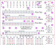
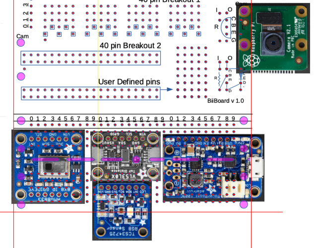
The top section of the Bii Board is shown below, first empty, next with the Pi 3 or 4 computer connected, then with the Pi Zero, and finally with the Pico. These signals are also available in the middle section. The top section is also designed so the edges of the Bii Board align with the edges of the computer being used. This makes it easy to plug in things. The top section also has a row of Jumpers discussed later. For convenience we will refer to the Pi 3, and Pi 4, and Pi Zero computers as Pi 340. The Pi 340's output pins have identical signals. (Pictures are take from several different versions.)
Top Empty
Pi 340 (Pi 3, Pi 4 or Zero)
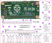
Pi Zero
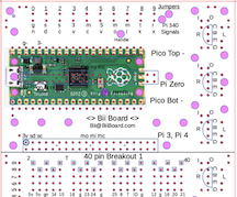
Pi Pico
The millipede in the center of the figure below makes all the signals from the computer available for breadboarding. If a Pi 340 computer is conneted, the BCM numbers (Broadcom computer) and other functions are shown above and below the millipede holes. For example the upper left legs of the millipede are 5 V, 5 V, GND, BCM 14, and BCM 15. The upper left leg is physical pin number 2. The Pico has completely different numbering and the Pico upper left legs are numbered 40, 39, 38, 37, 36.
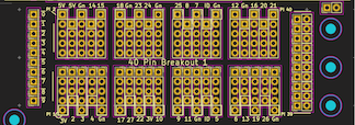
Top of Middle Section Showing the Millipede (40 Pin Breakout 1) @Millipede4-5.png
An LED and resistor can be placed between any of the grounds (labled Gn) and one of these signal to see it's state. (A convenient LED resistor pair is the Visual Communications Company, model 4302F5-5V, Digikey part number 4302F5-5V-ND.)
To the left of the millipede are the Jumpers. These holes are also replicated in the top and bottom sections as shown below. All of the 0 holes are interconnected, and all of the 1 holes interconnected ... . Having the commonly used signals available in each section makes wiring easier, reduces the mess of wires and makes trouble shooting much easier. Also large ground or supply currents can be carried around the Bii Board with wires between these Jumpers.
To the right of the millipede are a series of holes that can conveniently connect eternal wires to the Bii Board. The red line on the top set of holes shows the interconnections. The blue circles show holes available for 2-56 or m2.5 mounting screws.
The figure below shows the bottom of the middle section of the Bii Board. The 40 Pin Breakout 2 shown has the same pinout and orientation as the millipede and can be used to transfer these signals to another board. For example, an Adafruit 2822 can be soldered into these holes and an Adafruit 1988 ribbon cable used to transfer the signals to another Bii Board or to another breadboard.
In a similar manner, the User Defined Pins can be used to move other signals off the Bii Board. The array-of-holes to the right provide a convenient way to connect to these User Defined Pins. Here the small numbers show the connection between the User Defined Pins and the array-of-holes. For example the User Defined Pins the pin labled 5 is connected to the array-of-holes labeled 5. Also note that the Jumpers are also available on the bottom left of the User Defined Pins.
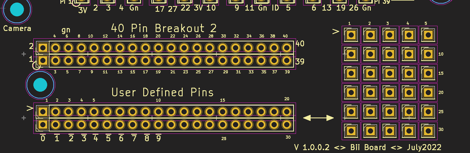
Lower Portion of the Middle Section -- Communication with Other Devices @Millipede4-5.png
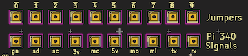
The Jumpers and Pi 340 Signals in the Top Section of the Board
Commonly used computer signals can be easily connected to the Jumpers using the holes below the Jumpers. For example, the ground signal from a Pi 340 computer is made available at the hole labled gn. Connecting gn to 0 makes the ground available on all 0 holes. The other computer signals are SDA1, SCL1, 3.3 V, SPI_CLK, 5 V, MOSI, MISO, TXDO, RXDO. Below is a table giving the Pi 340 signal name, the pin number, and the function. Also given is the pin number if a Pico computer is connected.
Jumper Wires in the Top Section -- @Jumpers_Top5.png
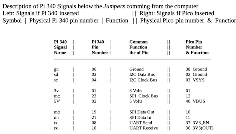
Table of the Pi 340 and the Pico Jumper Signals
There are so many different ways to use the bottom section of the Bii Board, it is hard to describe. So, I think it better to give examples.
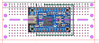
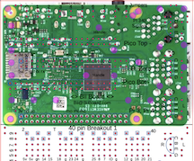
The Green and Black Wires Show the Breakout Board Connected to Power and Ground @Bottom1.png
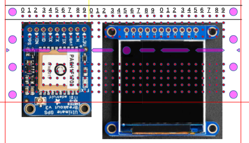
A GPS System and Display @Bottom2.png
Loaded for Bear, Many Sensors in Use @Bottom3.png
Every One is Needed -- To Make It Grand
I have had the excitement of being involved in half a dozen startup companies. In these companies, the Venture Capitalists always want to see the Private Placement Memorandum and pro forma financial spreadsheets. I have found these to be most helpful in understanding how to approach a new venture and the resources needed. So when I started this project, I spent several months writing these documents, sans all the pretty pictures and fancy words.
I do my financial spreadsheets using numeric switches. This allows me to change the price, or volume, or cost of manufacturing facilities by just changing the value of the switch. The spread sheet then automatically changes all the values and recalculates everything. This makes it easy to explore many models. For example, one model might be low volume, high price, with large marketing costs. Put in the switch numbers, and get the result.
Surprisingly this company was bimodal. At low volume, high price (like $10,000 or 20,000 per device), and high marketing costs, the company did make some profit. On the other end, high volume (like 10 to 100 devices per month -- no matter how you model this, it is a small market), almost no marketing, and reasonable prices, the company makes enough to pay several employees. I don't want to sell to just the few and wealthy; my goal is to help many people. And I like the high volume and low price model. (Done as a VC company, with all the marketing and hype, the financials suggested that it is a 6 to 12 person company requiring many millions in funding. A good part of this effort has nothing to do with developing a product, but goes into raising money, reports, demos, lawyer fees, and so on.)
Anyway, I went to the venture community with my high volume, lost cost model and said, "This is a great company that can do much good, but you aren't going to make a lot of money." I was well received by Venture Capitalists and they gave many good suggestions and encouragement. But their answer was always, "That's a great company, but I don't want to invest." I knew that before I started, but why not try anyway.
So, where do I go? There are many orphan companies like this, that can make things of great need and perhaps make a small profit, which don't succeed. I was, I still am, looking for a model on how to successfully develop these orphans into a market success.
So my approach was sweat equity. Just get on the lab bench and make it happen. I have spent years working on this project. I suspect many would suggest my continued attempts show a bit of my stupidity. I can't disagree. But I am stubborn and hate to quit something I believe in.
Even I now realize this is not a one person effort. And I've played with many other models on how to make this work as a conventional company. Unsuccessfuly, I might add.
Instead of a conventional company, I decided to open all the software under an open source license. Here anyone is free to use any software or extend it. My hope is this should greatly expand the number of people and development resources. I want to make these devices available to the blind.
I also feel a sense of relief. I don't have to develop all the stuff myself. This frees me to look for government funding for the different research groups, explore how to find novel Acoustic Cybers, and to help form collaborations between the diverse disciplines needed. I am looking forward to working with interested people.
This open source approach is the reason for the Bii Board's development. Two groups can design different aspects of the project, and their Bii Boards joined using the 40 pin connectors. And a third group can easily cobble these boards together with new software. The modularity of the Bii Board is a bit like the early microcomputers, you learn the system once, and then many things can be rapidly made from it.
I believe each group patenting their work would be a disaster. Group A patents a b c and group D patents d e f. This makes a product with a b e f almost impossible! Also groups A and D are running marketing campaigns and filing lawsuits. These costs are not paid for by the companies; they are paid for by the consumer in increased prices.
A word about the software and user interface. Many of the people becoming blind are elderly. Blindness must be huge change in a life already making many changes. If they actually do learn how to use our system, they want something simple, they want something that does not change. I propose two classifications of software code. 1) Base Line Code that everyone uses for every day common tasks. 2) Exotic Code that delight some people in all the different things that it can do. The Base Line Code is always there. It is what shows up when the machine is turned on. You can use the system well with only Base Line Code. The Exotic Code is there for experimentation and the advanced user. It provides sophistication for those enjoying that. It's more interesting. But it never modifies the Base Line user's experience.
I propose two rules for Base Line Code:
Trimmer's Two Rules: Simple and Never Change
I have designed and built a number of systems in my effort to help the blind. Each system taught me things. Each system made me want to build a better system. Below is a quick discussion of my learning process.
My first system was on a Macintosh laptop computer. Mark helped me get Python 2 and the software working. However, I can't see a blind person walking to the store while trying to type on a laptop computer. Our next system was on an Apple iPod. It was up and running making different sounds for different colors when Apple announced they were considering discontinuing the software application we were using. What a disaster that would be, blind people all around the world using this system, and all of a sudden, everything goes dead. (I like Apple Computers, this is just not the right application for a iPod.)
The Beagle Bone Black microcomputer seemed like a nice solution. It is an excellent, well conceived, designed and built microcomputer. Unfortunately, no matter what I did, it was too slow for our real time applications. I was getting ready to quit when Scott helped me switch to the Raspberry Pi 3 B computer. It does have the horsepower. For example, Abby and I were developing a GPS system on the Pi 3 B to help the blind navigate. The software used matrix mechanics mathematics to calculate distances and directions in three dimensional spherical coordinates. This is a heavy crunch and the Pi 3 B performed nicely with this real time application.
This new Pi 3 B system was satisfactory, but was about the size of a grapefruit. Not convenient to carry on your arm or chest or the tip of a cane. Recently, we developed the system using the Pi Zero. It is much smaller and convenient. However it barely keeps up with some basic computations. The software could be tweaked, or the programs written in C, to enhance the Zero's applicability. This is an open questions. (The recent Raspberry Pi Zero 2 W is small and has more computing power than the Pi Zero, but draws more current -- The Raspberry Pi Zero 2 is an unexplored option.)
I want to thank Scott Trimmer and Mark Trimmer and Abby Nutting for their wonderful efforts, love and support.
In conclusion, I do feel frustrated. I also feel hopeful. I believe this project is both doable and useful.
Thank you for reading this paper,
William Trimmer
Jump to Top of This This Web Page